Courses/Computer Science/CPSC 203/CPSC 203 Template/Lecture Template/Lecture 17
Contents
Housekeeping
Required Reading
Read and Enjoy George Boolos article, "The Hardest Logic Puzzle Ever" : [Boolos Article]
For Next Week:
- Fluency Chapter 10: "What's the Plan?. Algorithmic Thinking".
- Fluency Chapter 23: "computers Can Do Almost {Everything, Nothing}. Limits to Computation.
Introduction
We finish our look at Boolean Logic by examining how Truth Tables can be implemented as Digital Circuits. Each Boolean operator, corresponds to a specific Digital Circuit Diagram. By "wiring together" circuits corresponding to a particular diagram, we can build machines that implement boolean logic to solve specific problems.
At the end of this lecture you should:
- The basic Circuit Diagrams for Boolean Logic
- Be able to go between a "Truth Table" and a "Circuit" view of Boolean logic.
- Be introduced to a few more complex circuits.
Glossary
- Logic Gate -- Performs a Boolean logic operation on one or more inputs, and produces a single logical output. Logic Gates electronically emulate Boolean functions.
- Digital Circuit -- Realization of one or more logic gates as an electronic circuit.
- Circuit Diagram -- an visual representation of Logic Gates that standardizes the way we draw out circuits.
- DeMorgan's Laws. These laws express the idea of equivalence between different logical formulae.
- Not-(P and Q) is Equivalent to Not-P or Not-Q.
- Not-(P or Q) is Equivalent to Not-P and Not-Q.
- Double Negation Law. The idea that Not-Not-P is Equivalent to P.
- Note, there are a number of other equivalence laws that help us simplify logical statements, but which are outside the scope of this course.
Concepts
In Class Demonstrations
Continuing from last class, we will:
- Review several "Laws" of Boolean logic.
- Look at the process of creating a 3-valued logic that slightly extends Boolean Logic
- Introduce Circuit Diagrams as visual representations of Truth Tables.
- Introduce (briefly) the idea that the basic Boolean circuits can be wired together to create more complex circuits, which in turn can implement more complex logic.
Basic Logical Operators
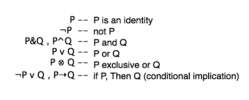
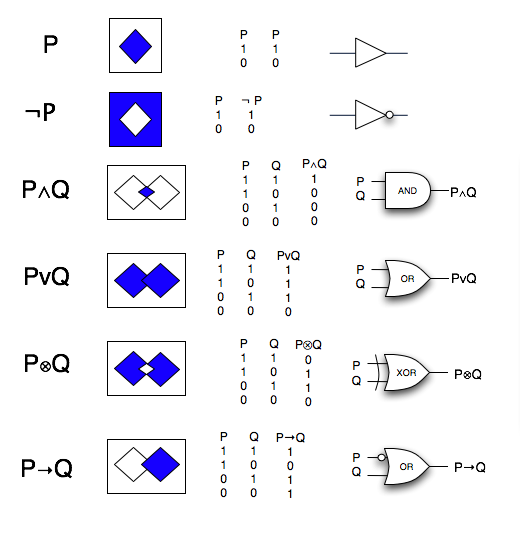
This is a summary of the basic Boolean Logic operators we have covered so far, from three different view points:
- Set Theoretic Interpretation
- Truth Table Representation
- Circuit Diagram Visualization of a Truth Table.
3 Views : Set Theory, Truth Tables & Circuits
Note: for P--> Q, the rectangle that surrounds the squares should be fully shaded.
Summary
- Circuits Diagrams visualize the implementation of Truth Tables as simple machines.
- From these simple machines, we can build more complex machines ( ..... and eventually computers).
- These machines are capable of making logical inferences, based on the Truth Tables they implement.
Some Web Resources:
- Truth Tables: Wikipedia: http://en.wikipedia.org/wiki/Truth_table(note that in class we used 1 where they use "T", and we used 0 where they use "F").
- Logic Gates: Wikipedia: http://en.wikipedia.org/wiki/Logic_gates.
- Booean Logic: Wikipedia: http://en.wikipedia.org/wiki/Boolean_Logic
Text Readings
See Required Readings above.
Resources
The primary resource for this lecture was:
- Ones & Zeros -- Understanding Boolean Algebra, Digital Circuits and the Logic of Sets. 1998. By John R. Gregg
Supplementary References are:
- Logic. A Very Short Introduction. 2000. By Graham Priest.
- Logic Made Easy. How to Know When Language Decieves You. 2004. By Deborah J. Bennett.
- Feynman Lectures on Computation. 1996. By Richard P. Feynman.
Homework
For each of the following Boolean algebraic expressions, draw the corresponding circuit diagram. If you wish extra practice, also write the Truth Table.
- Not-X or Y
- (X and Y) and Not-Z
- (X and Not-Y) and Not-X.
- X and Not-X.
- (X and Y) or (X and Not-Y)
- Not-X and Y

